
Blokland Installation Manual
BNF Optiprop/EasyStern GRP-stern tube with ClampSeals
Make sure the working environment is safe.
Before mounting the stern tube, first inspect the outer tube and check as follows:
- Both end surfaces of the outer tube must be machined rectangular (90° angle) in relation to the length direction of the tube.
- To prevent the propeller shaft seal to be installed out of line in relation to the stern tube.
- In case the outer tube end has been cut oblique and the rubber part of the ClampSeal is visible, the ClampSeal may come out of the outer tube.
- Both ends of the outer tube are not allowed to be too much deformed caused by e.g. welding.
- Welding to the outer tube must be carried out with care.
- The ClampSeal should be able to slide into the outer tube by hand, without the need of tooling/much force If necessary machine the outer tube ends to fit the ClampSeals using e.g. a sander.
- Clear both ends of the outer tube from burrs in order to allow the ClampSeals to slide in easily.
- Machine the outer tube ends with a grinder or half-round file until the ClampSeal inserts easily.
Mounting sequence of the GRP stern tube:
- Slide the GRP stern tube into the outer tube while leaving the machined end protruding the outer tube (Fig. 1).
- Note: The longest bearing (L=4x shaft diameter) to be positioned at the aft side (propeller side).
- The mark on the sticker at the front side of the GRP stern tube (Fig. 2) should face upwards.
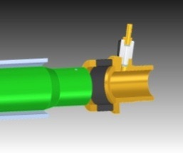
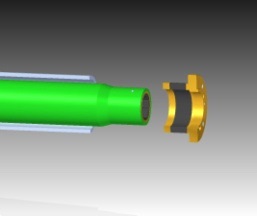
Fig. 2 (type VS) Fig. 1 (type MS) Fig. 2
- Slide the ClampSeal with shaft seal adapter (engine side) over the GRP stern tube, until it hits the edge inside the shaft seal adapter (fig. 3).
- Apply tallow on the outside as well as on the inside of the ClampSeal rubber, to extend the life span of the rubber.
- Slide the ClampSeal together with the GRP stern tube through the outer tube to the aft side (propeller side), until the flange of the shaft seal adapter hits the outer tube (Fig. 4).
- Note: The water supply/venting connection of the stern tube/shaft seal must face upwards! Rotate the front side ClampSeal to get the correct position of the water supply connection.
- Put the aft ClampSeal into position. The ClampSeal is now used to line the GRP stern tube with the outer tube (Fig. 5 + 6).
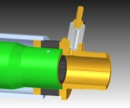
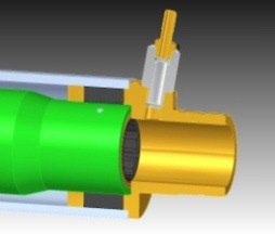
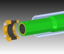
Fig. 3 (type VS) Fig. 4 (type VS) Fig. 5 (aft/prop. end)
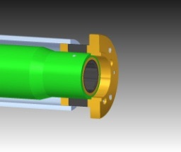
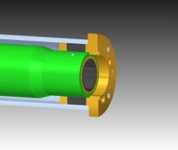
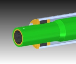
Fig. 3 (type MS) Fig. 4 (type MS) Fig. 6 (aft/prop. end)
- In case a flexible shaft seal is mounted at the front side of the GRP stern tube (type FP; a ClampSeal without shaft seal adaptor): Position the GRP stern tube at the correct distances in length direction. Use the applicable system drawing (stern tubes are custom made!).
- The mark on the sticker at the front side of the GRP stern tube (Fig. 2) should face upwards.
- Tighten the allen screws of the ClampSeal at the front/engine side, in diagonal opposite order, 1/2 turn at a time, until these are hand-tightened (Fig. 4). Use the right tools to do this.
- Then fully slide the aft. ClampSeal into the outer tube until the flange hits the outer tube.
- Tighten the allen screws of this ClampSeal as well, also in diagonal opposite order 1/2 turn at a time, until they are hand-tightened (Fig. 7).
- When both ClampSeals are installed, tighten the allen screws in diagonal opposite order to the below mentioned torque values (use a suitable torque wrench):
|
Propeller shaft diameter (mm) |
Screw diameter |
Tightening torque (Nm) |
|
Ø25 – ø30 |
M5 |
6 |
|
Ø35 – ø40 |
M6 |
10 |
|
Ø45 – ø60 |
M8 |
25 |
|
Ø70 – ø80 |
M10 |
50 |
|
Ø90 – ø180 |
M12 |
80 |
Fig. 7
- Re-torque the allen screws 24 hours after installation!
In case the GRP stern tube length is over 3500 mm, it needs to be additionally fixed in the outer stern tube by means of special supplied adjusting screws with thin nut.
- Mount the adjusting screws at the correct position (approx. halfway the length), 3 screws around the circumference of the outer tube.
- Position the screws e.g. one at the down side and the others at the side, positioned just above the outer tube center line (for the correct position please refer to the system drawing supplied with your quotation or order confirmation).
- At least one screw should remain accessible (e.g. the on at the down side)to keep the stern tube dismountable.
- Mount the GRP stern tube in the outer tube as described earlier (do not yet insert the propeller shaft!).
- Carefully turn the adjusting screws one by one by hand until they just hit the GRP stern tube.
- To prevent leakage through the thread holes, use a suitable sealing agent (e.g. white Loctite 572) and apply this on the three locking screws.
- Align the middle bearing in the GRP stern tube by turning the adjusting screws.
- At last turn all three locking screws ± ½ turn extra and secure them using the hexagon thin nut.
- Use a proper tool to prevent the locking screw from rotating while doing this. The GRP stern tube now is fixed into the outer tube.
When sliding the propeller shaft into the stern tube, use following directions:
- Lubricate the shaft with liquid soap and water for easy installation (water lubricated systems only!).
- Make sure the stern tube is well aligned with the thrust bearing and/or the gearbox output flange. To check proper alignment, the shaft should be able to rotate by hand without too much resistance (in lubricated condition). o If needed, change the fixation of the GRP stern tube (middle bearing), using the three locking screws.
- Install the propeller shaft seal onto the stern tube (refer to applicable shaft seal manual).
- Fix the propeller shaft to the thrust bearing (e.g. Aquadrive) or gearbox output flange o Position the key(s) into the corresponding shaft keyway using a plastic hammer.
- Install the propeller onto the propeller shaft end.
- Make sure the tapered surfaces are clean and without any damage.
- If necessary, re-machine the surfaces or grind the surfaces to fit using e.g. diamond-paste)
- Mount the propeller nut on the shaft and secure it with the supplied set screw.
- Only one set screw is supplied. It should be installed into one of the two propeller nut thread holes. In case the set screw is in front of the keyway or thread hole in the propeller boss, use the other propeller nut thread hole. Apply a suitable locking agent (Loctite)to secure the set screw.